
1. Overview
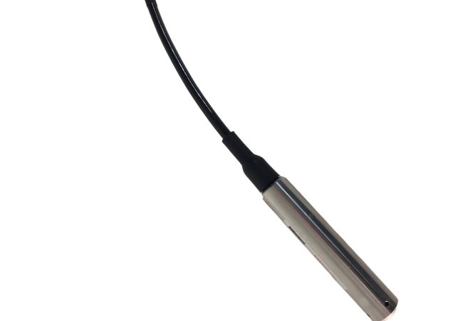
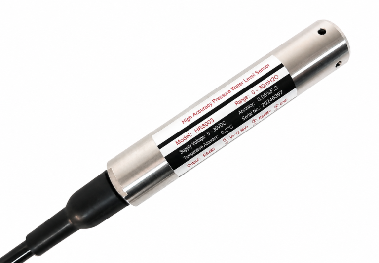
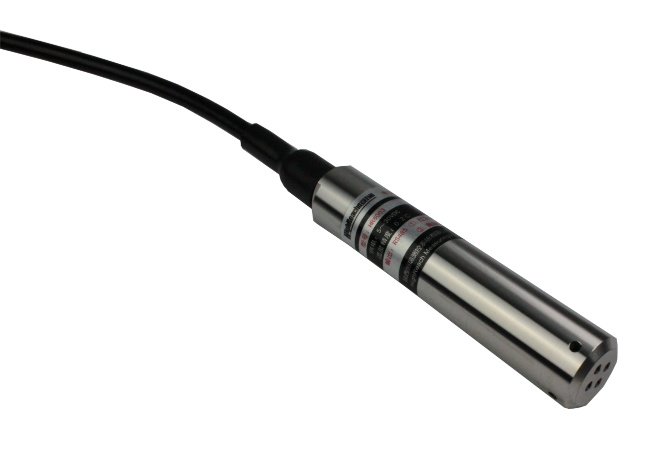
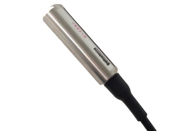
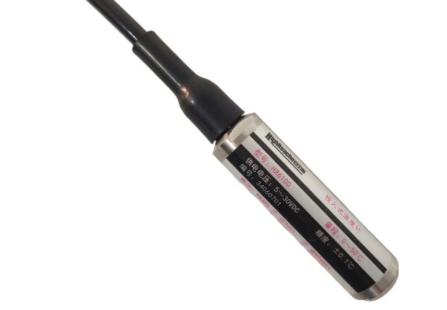
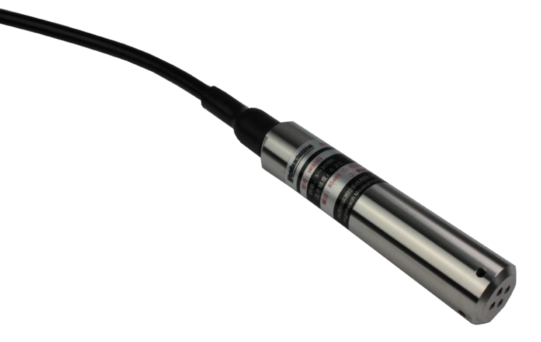
BT8003 water level transmitter is one kind of pressure water level gauge used for measuring water level and temperature. With mixed-signal processing technology, it overcomes the shortage of traditional analog circuit modules realizes F S digital linearity correction full temperature digital temperature compensation compensation data stored in nonvolatile memory multiple safety protection system to avoid the products cannot be used due to correction data lost; Circuit part with power and watchdog monitor which improve the reliability of the transmitter.
Rich product line; it is widely used in water level and temperature measurement of industrial processes, mining, hydrology, water conservancy, geological exploration, and other industries.High-quality and stable sensing elements.
Click Here to Down Load User Manual.
2. Features
- Anti-surge electromagnetic interference
- Integral measurement of level and temperature
- Reverse power protection over voltage protection
- FS digital calibration and temperature compensation
- RS485 interface and MODBUS-RTU standard protocol
3. Main Applications
-
Groundwater & Deep Well Monitoring: Its slim, compact diameter allows for effortless installation in narrow boreholes and deep wells, providing highly precise long-term tracking of groundwater tables and aquifer temperatures.
-
Hydrological & Surface Water Surveying: Ideal for continuous water level recording in rivers, lakes, reservoirs, and open channels. It effectively overcomes traditional analog circuit drift, ensuring accurate data for flood warning and water resource management.
-
Industrial Tank & Reservoir Storage: Perfect for measuring the level and temperature of water, mild chemicals, and processing fluids stored in industrial tanks, closed vessels, or outdoor reservoirs.
-
Municipal Wastewater & Water Treatment: Applied in urban drainage networks, sewage treatment plants, secondary water supply systems, and rain pump stations to optimize pump control and ensure seamless water distribution.
-
Environmental & Climate Monitoring Systems: Seamlessly integrates with telemetry systems, micro-weather stations, and remote terminal units (RTUs) via RS485 Modbus-RTU protocol for unattended, automated data collection.
4. Technical Parameters
|
Main performance specification |
|
|
Accuracy |
<±0.05% F·S |
|
Range |
0~10 mH2O…200 mH2O |
|
Long-term stability |
<0.05%F·S/year |
|
Overload capability |
2X F·S |
|
Temp. Accuracy |
±0.2 ℃(0~70 ℃) |
|
Temp. Resolution |
0.01℃ |
|
Temperature characteristics |
|
|
Compensation temp. |
0~50℃ |
|
Operating temp. |
-10~80℃ |
|
Drift of temp |
Zero: <0.005%F.S/℃ |
|
F.S: <0.005%F.S/℃ |
|
|
Storage temp. |
-40~125℃ |
|
Electrical characteristics |
|
|
Power Supply |
DC3.8~30V (typ.24V) |
|
Power Protection |
Anti-reverse connection overvoltage protection |
|
Output method |
RS485/MODBUS-RTU protocol |
|
Structural characteristics |
|
|
Measuring medium |
Compatible with stainless steel and fluoro rubber |
|
Housing material |
stainless steel 316L |
|
Cable material |
Polyurethane or PVC optional |
|
Cable |
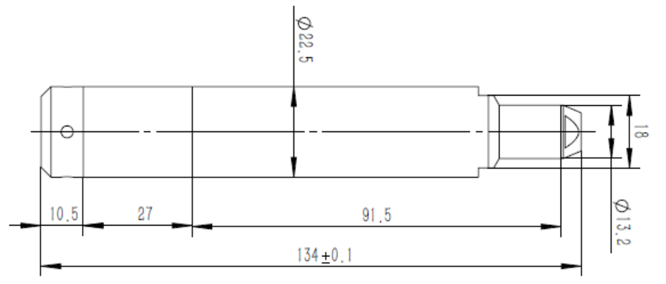
Φ7.6mm,with Shielding layer and guide hole length customized |
|
Environmental characteristics |
|
|
Protection level |
IP68 |
|
Insulation |
100MΩ@50V |
5. Related parameters
6. Operating Instructions
6.1 Power Supply
The external power supply of the instrument can be as low as 5VDC and as high as 30VDC. It has reverse connection protection function and supports intermittent power supply operation.
6.2 Communication Interface
The instrument adopts an industrial-grade RS485 communication interface, working in a half – duplex master – slave mode.
The transmission distance can reach 1200 meters. The supported baud rates are 9600, 19200, 38400, and 57600.
Serial Port Number: The serial port number of the communication serial port, with the default value of COM1. Set it according to the actual serial port number connected to the computer during use.
- Baud Rate: The baud rate of the communication serial port, which can be selected from 9600, 19200, 38400, 57600 (Bit/s), with the default value of 9600.
- Parity Bit: The parity check method of the communication serial port, including no parity, even parity, and odd parity, with the default value of no parity.
- Stop Bit: The stop bit of the communication serial port, which can take values of 1 or 2, with the default value of 1 bit.
- Data Bit: The data bit of the communication serial port is fixed at 8 bits.
The supported communication protocol is the MODBUS – RTU protocol. After the external power supply is turned on, the instrument can be operated by sending commands through computer software or a MOD-BUS host (such as an RTU device), such as collecting water level and temperature values.
6.3 Fixing
The instrument has an integrated submersible structure with a shielded air-guiding cable. Since the cable is usually long, steel wires are added to the cable to increase its tensile strength and improve reliability. After the instrument is put into the logging well, the probe is mainly suspended at the wellhead of the logging well through the cable. When fixing, the steel wire should be firmly tightened so that the gravity mainly acts on the steel wire.
When installing at the wellhead, a protective cover should be equipped to protect the side of the cable connector to prevent the air – guiding tube from being blocked (the absolute pressure type has no air – guiding tube), and connect the shielding wire properly.
7. Wiring
7.1 Instrument Wiring
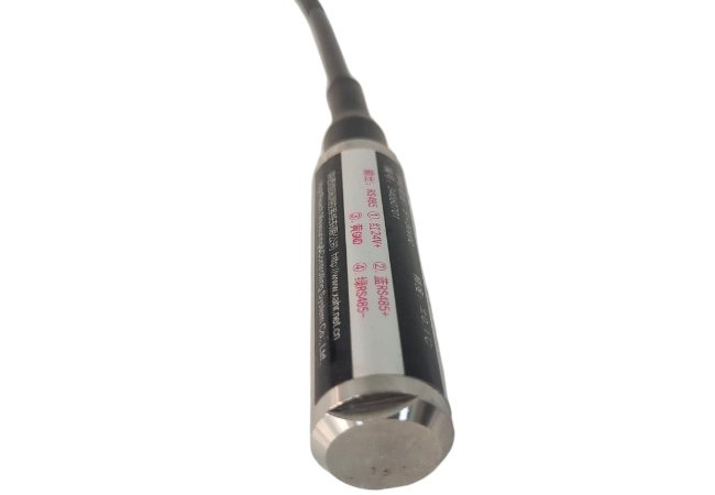
The power supply and communication of the instrument share a four – core cable. The wires are in four colors: red, white, blue, and green. Red and white are the positive and negative of the power supply, and blue and green are the positive and negative of the RS485 signal.
7.2 Connecting to a Computer
The following accessories are required to connect to a computer:
– RS232<->RS485 converter
– USB<->RS232 converter
Or
– USB<->RS485 converter
Connection method: Connect the blue wire of the cable (RS485 – A) to the RS485+ (T+) of the converter; connect the green wire of the cable (RS485 – B) to the RS485- (T-) of the converter; plug the USB cable directly into the USB port of the computer. You can view the corresponding serial port number in the Device Manager and use this serial port number in the computer software.
8. Setting
8.1 Communication Settings
When using the instrument for the first time, pay attention to whether the communication parameters are correct, mainly referring to whether the serial port settings of the computer or the MODBUS host are consistent with those of the instrument. The default serial port parameters of the instrument when leaving the factory are: 9600, 8, n, 1; the default communication address is “1”.
Once the communication parameters of the instrument are changed, they take effect immediately (no need to power off). At the same time, the communication parameters of the computer software should also be changed to the same parameters as those of the instrument immediately.
8.2 User Calibration
Users can adjust the water level zero point and density to adapt to the on – site measurement environment and medium. The instrument has been accurately calibrated before leaving the factory, and generally no adjustment is required. If calibration is needed, please carry it out under the guidance of technical personnel.
9. Data Collection
After connecting to a computer, RTU or other devices, collect data through the 03H function code in the MODBUS – RTU protocol in the software.
10. How to Use the MOD-BUS Protocol
10.1 For Users Connecting the Instrument through Software or Special Equipment Programming
For detailed instructions on the MODBUS – RTU protocol, register read – write operation commands, and register definitions, please refer to “Communication Protocol for Integrated Water Level and Temperature Recorder V3.1”.
10.2 For Users Connecting the Instrument with a Computer
9.2.1 You can use serial port debugging software and refer to the calling method in the “Communication Protocol” to operate the instrument.
9.2.2 You can use the debugging software provided by the instrument manufacturer for simple operations.
9.2.3 Users can develop their own special operation software.