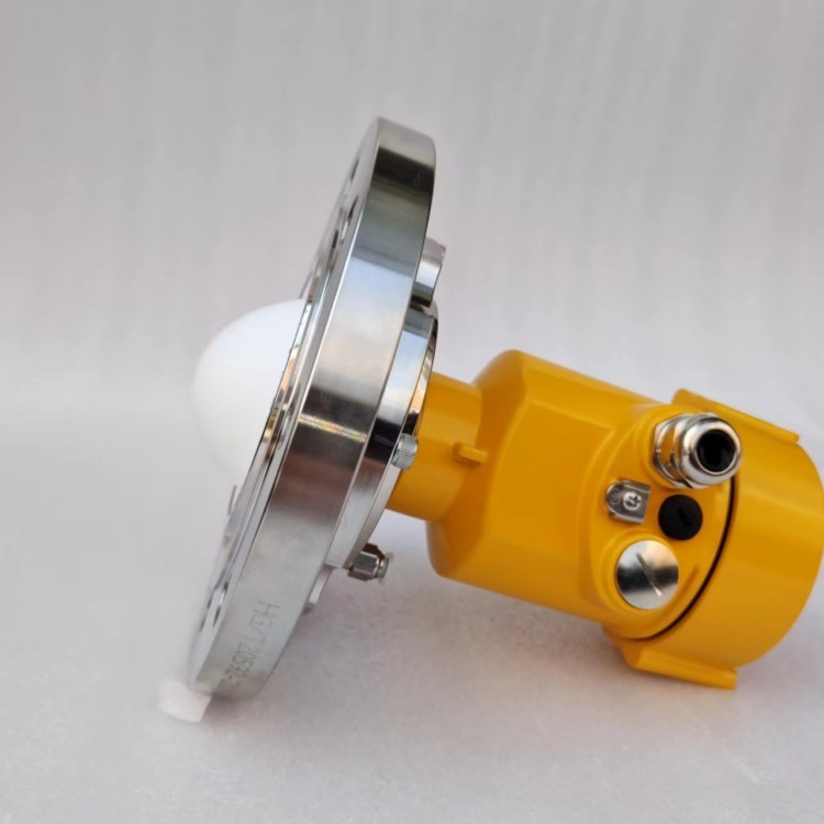
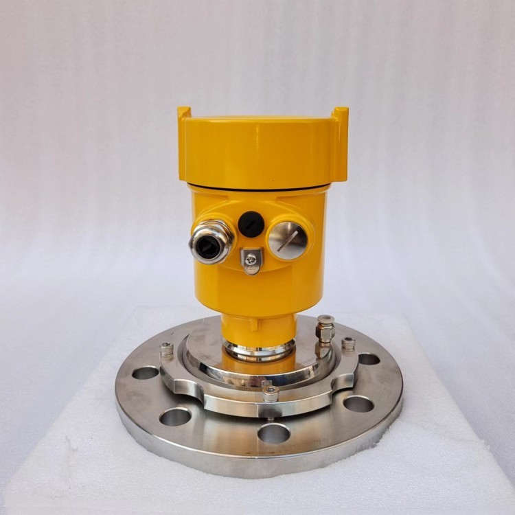
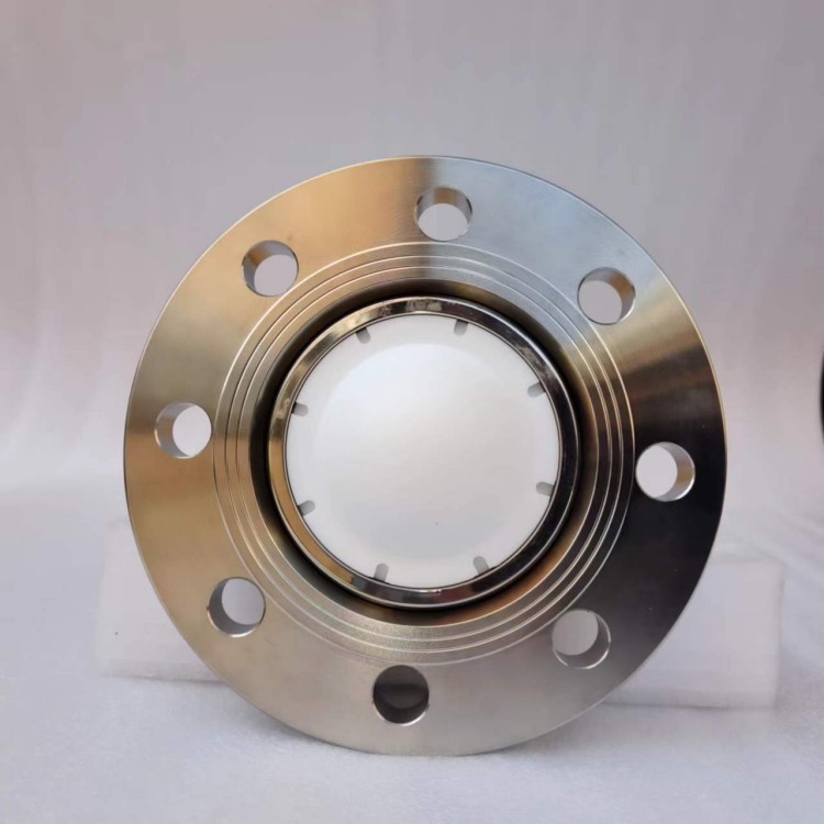
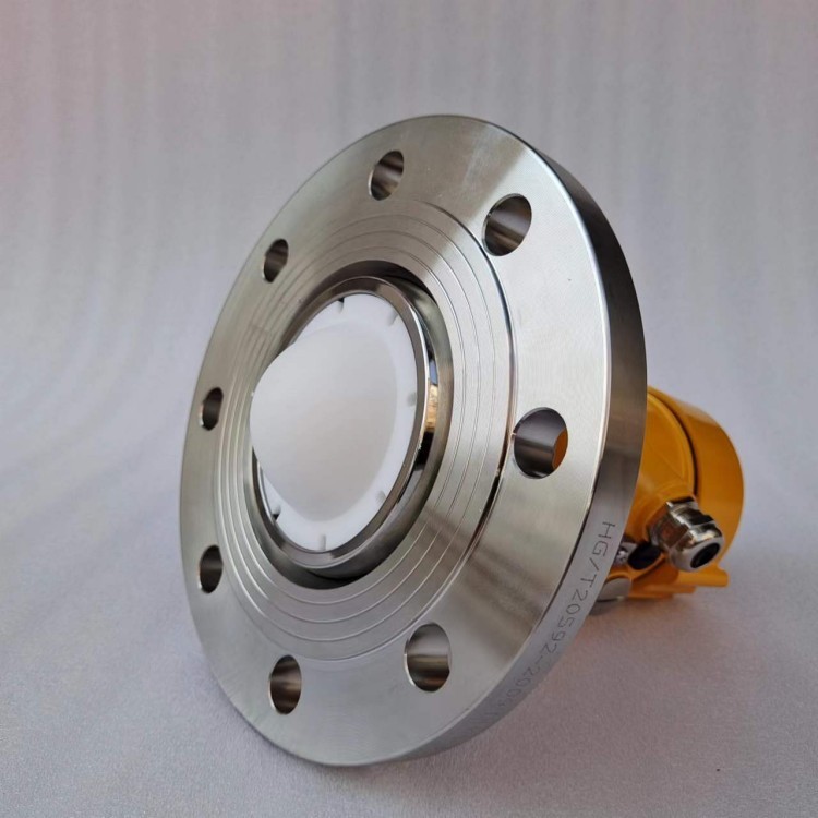
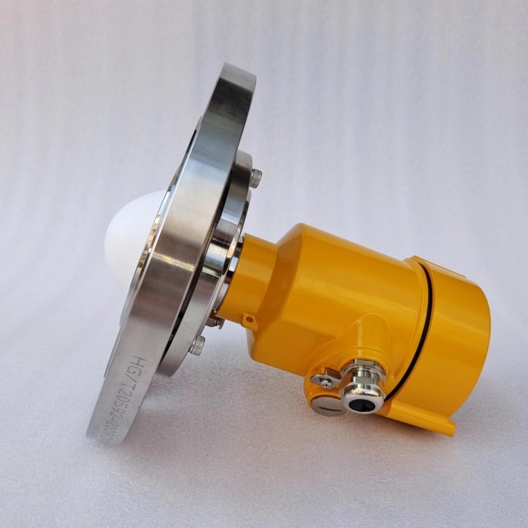
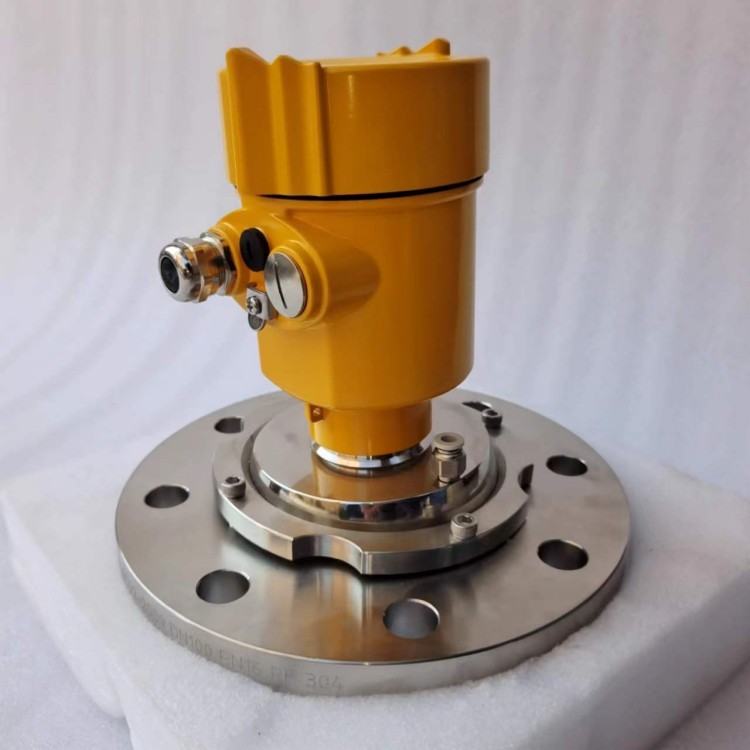
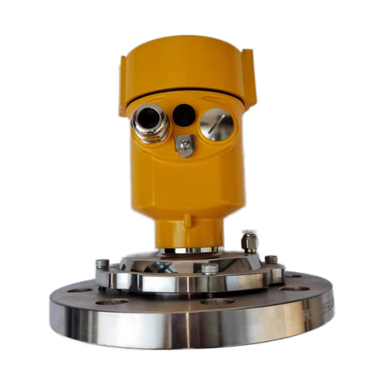
HR7380W 80 GHz Radar Level Transmitter with Omnidirectioanl Flanges
80GHz Radar Level Transmitter is a range of Frequency Modulated Continuous Wave (FMCW) radar products operating in the 76-81GHz frequency range. These transmitters support both 4-wire and 2-wire applications. The products come in multiple models with a measurement range of up to 120m.
1. Introduction
80GHz Radar Level transmitter is a range of Frequency Modulated Continuous Wave (FMCW) radar products operating in the 76-81GHz frequency range. These transmitters support both 4-wire and 2-wire applications. The products come in multiple models with a measurement range of up to 120m.
2. Advantages
※ Utilizes self-developed CMOS millimeter-wave RF chips, enabling a more compact RF architecture, higher signal-to-noise ratio, and reduced blind zones. It is unaffected by attenuation caused by steam and dust, and can provide stable measurements even for materials with weak reflection characteristics or low dielectric constants.
※ 5GHz working bandwidth, allowing for higher measurement resolution and accuracy.
※ Minimum 3° antenna beam angle, resulting in reduced impact from environmental interferences during installation, making it more suitable for challenging process conditions such as mixing.
※ Shorter wavelength, providing better reflection characteristics on solid surfaces, significantly reducing dependence on flange orientation.
※ Supports remote debugging and upgrading, reducing wait times and improving operational efficiency.
※ Supports Bluetooth debugging via mobile phones, facilitating on-site maintenance by field personnel.
※ The measurable temperature range of the medium is wide: (-40~100)℃;(-40~200)℃;(- 40~350)℃;(-40~1000)℃
※ The measurable medium can be either liquid or solid particles. In principle, it can accurately monitor the level for media with a dielectric constant greater than 2.
※ The omnidirectional purging function quickly and effectively cleans the lens surface from dust, frost, and fog, ensuring measurement accuracy.
3. Communication & Debugging
HR7380W can be debugged on-site using the LCD display or via PC-based software. Communication between the transmitter and a PC can be achieved through the following methods:
USB to RS485 serial cable (4-wire).
USB to TTL serial cable (2-wire).
USB to HART modem (2-wire) for communication.
Bluetooth debugging via mobile phones, ensuring safer and more convenient on-site debugging.
Remote debugging is also possible using the 4G network and a remote module.
4. Technical Specifications
Transmitting Frequency | 76GHz-81GHz |
Range* | 10m;20m;30m;60m;120m |
Accuracy | ±1mm |
Measurement Interval | Fastest 100ms |
Beam Angle | 3° |
Permissible Dielectric Constant Range | ≥2 |
Power Supply | 12-28.0VDC |
Communication Protocol | MODBUS, HART |
Signal Output | 4-20mA or RS-485 or TTL |
Fault Output | 3.8mA, 4mA, 20mA, 21mA (hold) |
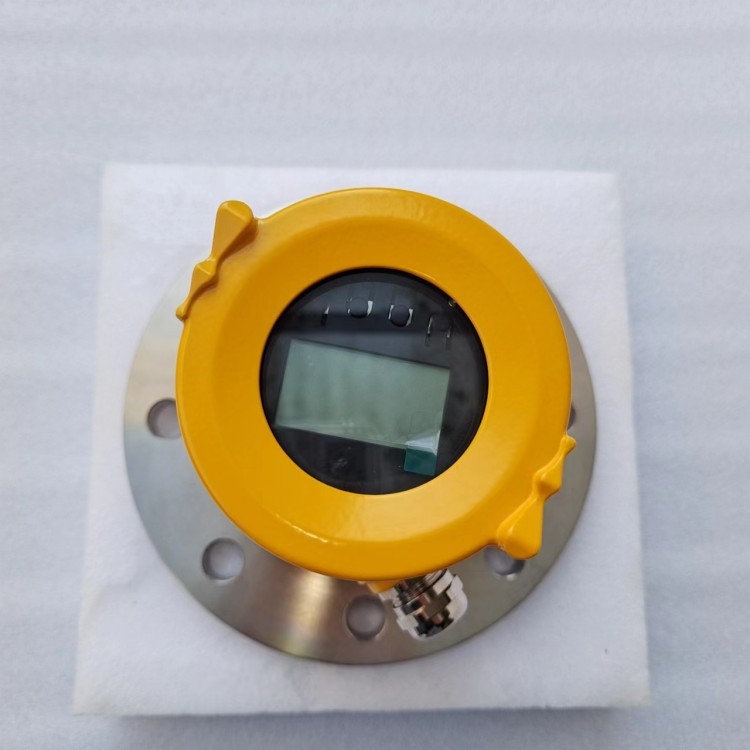
Field Operation/Programming | 128×64 dot matrix LCD display/4 buttons; can be configured using PC-based software |
Process Temperature/Humidity | T0: -40-85℃/humidity ≤95%RH; T1: -40-200℃; T2: -40-500℃; T3: -40-1000℃ |
Control Unit Operating Temperature | -20-70℃ |
Housing Material | Aluminum alloy, stainless steel |
Process Connection | Threaded, flanged (universal, sanitary clamp), quartz isolation flange |
Process Pressure | -0.1-2MPa |
Cable Entry | M20*1.5 |
Recommended Cable | AWG18 or 0.75mm² |
Protection Class | IP67 |
Installation Method | Threaded or flanged |
Note: The measurement blind zone is dependent on the selected antenna and the reflection characteristics of the measured object. Laboratory blind zone testing is based on either water surface or metal plate.
5. Structure
5.1 Beam Angle 3°, ambient temperature, omnidirectional purging, equipped with DN80 flange.
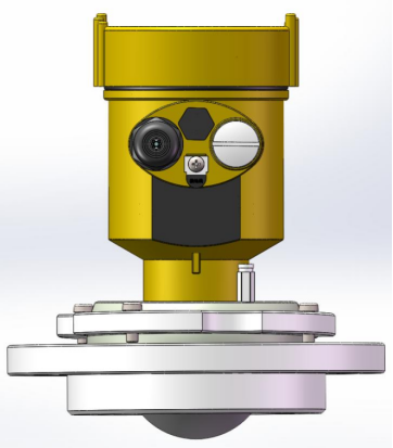
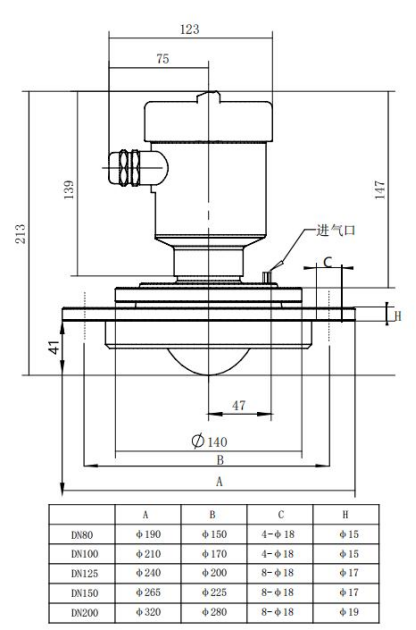
5.2 Beam angle: 3°, temperature range: -40~200℃, omnidirectional purging, equipped with DN80 flange.
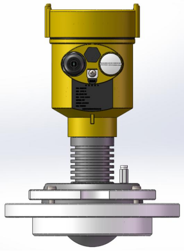
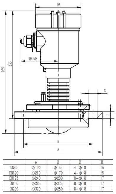
6. Installation
Here are a few installation considerations:
♘ For liquid applications, it is preferable to install the flange parallel to the liquid surface, ensuring that the emitted electromagnetic waves are perpendicular to the liquid surface.
♘ For solid applications, if the material surface is relatively flat, a parallel installation can be chosen. If the material has a significant pile-up angle and a small measurement dead zone is required, it is recommended to use an omnidirectional structure to adjust the emission direction, making it nearly perpendicular to the inclined material surface.
♘ During installation, it is important to avoid any obstructions within the radar beam range, such as stirring blades or protrusions. These obstructions can generate interference signals and affect the normal operation of the radar. Please refer to the typical operating conditions shown in Figure 6-1 to ensure that there are no obstructions within the beam range, such as ladders or steps.
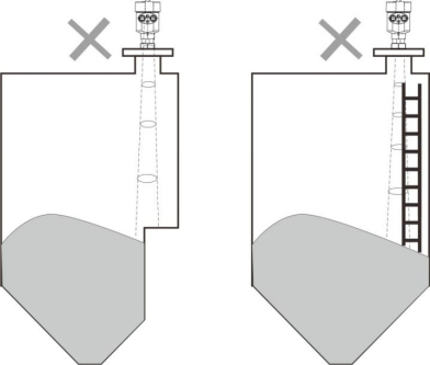
Figure6-1 Ensure there’s no obstruction within the beam angle.
The instrument installation should ensure that the antenna beam is directed away from the inlet, as shown in Figure 6-2.
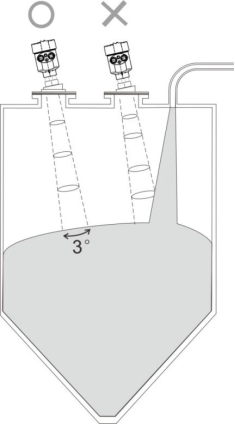
Figure 6–2 The antenna beam should be directed away from the inlet
The instrument should be installed at least 200mm away from the container wall to avoid potential error readings, as shown in Figure 6-3.
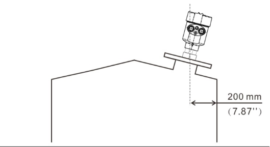
Figure 6–3 Transmitter should be installed at least 200mm away from the container wall
For conical containers, if you want to monitor the entire filling and emptying process, it is recommended to use an omnidirectional flange and ensure that the beam is directed towards the bottom of the tank, as depicted in Figure 6-4. This helps to obtain accurate measurement results at the bottom of the tank. However, if the bottom level can be disregarded, there is no need to use an omnidirectional structure.
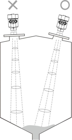
Figure 6-4 For conical contaiers, ensure that the beam is directed towards the bottom of the tank
More details, pls click here to download:
INQUIRY
CATEGORIES
LATEST NEWS
CONTACT US
Contact:Roxy Deng
Phone:+8617794001501
Tel:+8617794001501
Email:roxy@besteetech.com
Add:Weibin District, Baoji, Shaanxi Province, China
 Roxy Deng
 Roxy Deng