
1. Overview
Click here to download the datasheet.
The BT6200 temperature transmitter incorporates an imported temperature-sensing element, utilizing computer-guided laser resistance trimming for precise temperature compensation. Designed with an integrated junction box, it features dedicated terminal blocks and a digital display for effortless installation, calibration, and maintenance.
This series is engineered for fluid temperature measurement across various industries, including petroleum, water conservancy, chemical processing, metallurgy, electric power, light industry, scientific research, and environmental protection. It is suitable for all-weather applications and compatible with diverse corrosive fluids.
2. Main Features
- Flexible Range Options: Multiple temperature ranges available.
- Clear Digital Display: Digital LCD display for real-time temperature reading.
- Easy Calibration: Convenient span and range adjustment.
- Circuit Protection: Built-in reverse polarity and current-limiting protection.
- Rugged & Reliable: Anti-lightning, transient, and impact resistance.
- Safe & Compact: Intrinsically safe explosion-proof design, compact footprint, aesthetic appearance, and high cost-performance ratio.
- High Performance: Outstanding accuracy, stability, and operational reliability.
3. Technical Specifications
| Parameter | Specification |
| Temperature Range | -50 °C ~ 400 °C |
| Accuracy Class | ±0.5% F.S. |
| Overload Capacity | 150% F.S. |
| Output Signal | 4–20 mA / RS485 |
| Long-Term Stability | ≤ 0.1% F.S./year |
| Power Supply | 18–36 VDC |
| Display Mode | 5-digit LCD |
| Display Range | -19999 ~ 99999 |
| Ambient Temperature | -20 °C ~ 70 °C |
| Relative Humidity | ≤ 80% RH |
| Mounting Thread | M27*2 (Optional) |
| Wetted Material | SS304 / SS316 Stainless Steel |
4. Dimensions
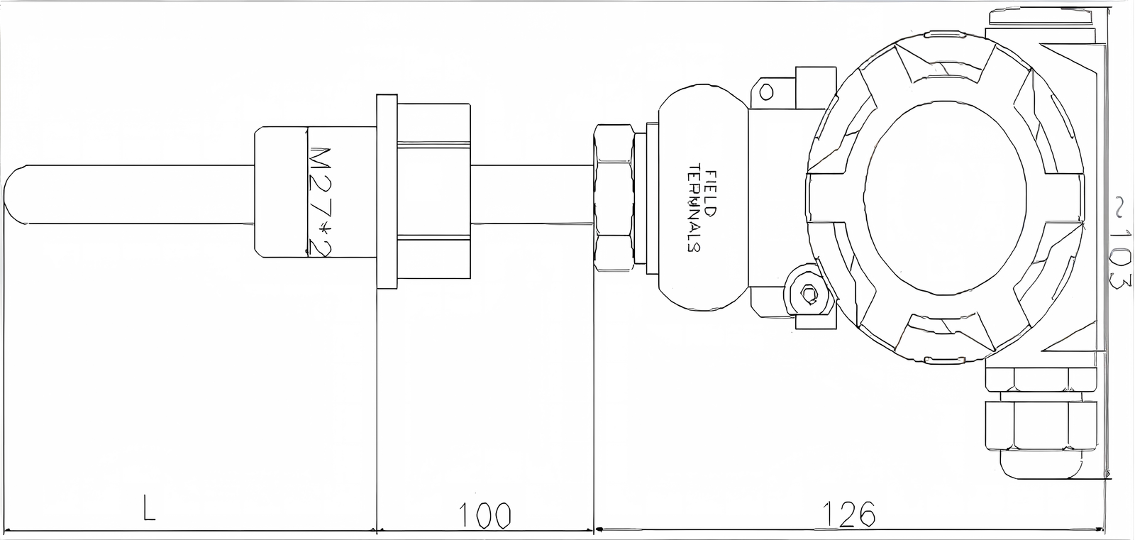
(L: User-defined)
5. Applications
Petrochemical & Oil:
Pipeline fluid temperature tracking in harsh chemical environments.
Water Conservancy & Hydrology:
Water treatment plant process monitoring and thermal tracking.
Industrial Automation:
HVAC, power plants, metallurgical processing, and scientific research laboratories.
6. Electrical Connection
The signal terminals are located in a separate compartment inside the terminal box. For wiring, unscrew the cover on the terminal side. Power is supplied to the transmitter through the signal lines; no additional wiring is required.
Twisted-pair wires can be used for signal lines. In environments with severe electromagnetic interference, shielded cables are recommended and must be properly grounded. Signal lines should not be routed through metal conduits or placed in the same wire troughs as other power lines, nor should they pass near high-power electrical equipment.
The conduit entry hole on the transmitter box should be sealed or plugged (using sealant) to prevent moisture accumulation inside the enclosure. If the conduit entry is not sealed, the transmitter should be installed with the entry hole facing downward to allow liquid drainage.
The signal line can be left floating or grounded at any point in the signal loop. The transmitter housing may also be grounded or un-grounded.
Because the transmitter is grounded through capacitive coupling, do not use a megohmmeter with a voltage higher than 100V to check insulation resistance. Circuit checks should be conducted using a voltage no greater than 45V.
7. Menu Settings
General User Menu
The access password is 00001, which allows setting the display unit, display resolution, and display mode.
Unt (User Unit Setting):
Configurable range (0–4). There are 5 display unit options available: °C, °F, K, °Ra, and °Re.
dot (Display Resolution Setting):
Configurable range (0–2). The menu prompt displays the current temperature unit. The display resolution determines the number of decimal places shown in measurement mode. Users can configure this based on site requirements. A higher number of decimal places is not always better; stability of the displayed value should be prioritized. Additionally, this setting is limited by the transmitter’s maximum display value calibrated at the factory. If the configured decimal places cause the maximum value to exceed the 5-digit display limit, the decimal places will be restricted to ensure normal display.
Example: If the transmitter calibration range is 0.0000–20.000 MPa, the accuracy setting range is (0–3). If set to 4, the maximum value would exceed the 5-digit limit.
SHO (Display Mode Setting):
Configurable range (0–5).
0: Displays primary variable, prompt -PV-
1: Displays current output, prompt -mA-
2: Displays percentage, prompt -%-
3: Alternates primary variable and current output, prompt PV-mA
4: Alternates primary variable and percentage, prompt PV–%
5: Alternates current output and percentage, prompt mA–%
8. Precautions
- Wire the transmitter correctly according to the wiring diagram. If reverse-connected, internal protection circuits will prevent signal output. The transmitter works immediately upon powering on, but a 30-minute warm-up ensures a stable and reliable output signal.
- The maximum temperature of the system under test must not exceed the rated overload capability.
- This product is a precision primary measuring instrument. Dropping, forceful clamping, or unauthorized disassembly is strictly prohibited.
- Install the instrument in a well-ventilated, dry, non-corrosive, and shaded location whenever possible. If field conditions are harsh, take appropriate protective measures.
- In case of abnormal output, halt operation for inspection. If it is a product quality issue, return the transmitter to the factory along with the warranty card and user manual for repair or replacement.
- Non-professional personnel should not disassemble the circuit board or modify internal devices.