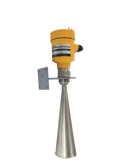
HR7301/02 Radar Water/Mud Level Guage
Ⅰ. General Introduction
HR7301/2 radar level transmitters emit narrow microwave pulses from their antennas. These pulses propagate at the speed of light in space and when they encounter the surface of the measured medium, a portion of their energy is reflected back and received by the same antenna. The time interval between the transmitted and received pulses is directly proportional to the distance between the antenna and the surface of the measured medium.
Due to the extremely high speed of electromagnetic wave propagation, it is challenging to accurately determine the time interval between the transmitted and received pulses, which is on the order of nanoseconds. The HR7301/2 radar level transmitters employ a special demodulation technique that allows for precise identification of the time interval between the transmitted and received pulses, enabling accurate calculation of the distance from the antenna to the surface of the measured medium.
Ⅱ.Product Features
þThe narrow beam angle of the radar level transmitter allows for concentrated energy, providing strong resistance to interference and greatly improving measurement accuracy and reliability.
þThe small antenna size facilitates installation and the addition of protective devices such as dust covers.
þWith a lightweight design of approximately 1kg, it is easy to install.
þThe measurement range can reach up to 70 meters, making it suitable for large-scale water level measurements in reservoirs and other applications.
þIt offers multiple output circuit interfaces that can be integrated with data acquisition systems.
þUsing a pulse operating mode, the radar level transmitter emits extremely low power, posing no harm to humans or the environment.
Ⅲ. Technical parameters
Main Specifications | Blind Area | End of the Antenna | |
Max. Measuring Dicetance | HR7301 | 30m | |
HR7302 | 70m | ||
Microwave Frequency | 26 GHz | ||
Communication Inferface | ModBUS | ||
Measuring interval | ≈ 1s | ||
Adjusting Time | ≈ 1s | ||
Display Resolution | |||
Working/Storage/Transpotation Temp. | (-40~100 )℃ | ||
Process Temp.(Antenna) | (-40~250 )℃ | ||
Pressure | Max. 4MPa | ||
Shock-proof | Mechanical vibration of 10m/s⋙ | ||
Power Supply | Standard | (6~26)VDC | |
Consumption | max 12mA | ||
Allowed Wave | -<100Hz | Uss<1V | |
-<(100-100k)Hz | Uss<10mV | ||
Output Parameters | Output Signal | RS485 | |
Communication Protocol | Modbus | ||
Resolution | 1.6 u AC | ||
Breakdown Signal | Current output remain unchanged | ||
20.5 mA | |||
22 mA | |||
3.9 mA | |||
Integral time | (0-50)s, adjustable | ||
Housing | Sealing between outer cover and shell | Silicon rubber | |
Shell Window | Polycarbonate | ||
Ground Terminal | Stainless Steel | ||
Cable Parameters | Cable entry/plug | M20*1.5 Cable entry | |
Connecting Terminal | Wire Cross-section 1.0 m㎡ |
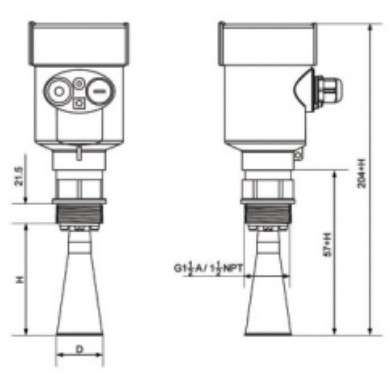
Ⅳ. Dimensional structure(Unit:mm)
HR7301
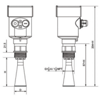
Flange | Bell Mouth Diameter | Bell Mouth Height |
DN50 | φ46 | 140 |
DN80 | φ76 | 227 |
DN100 | φ96 | 288 |
HR7302
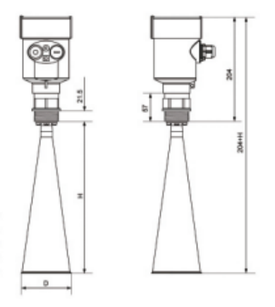
Flange | Bell Mouth Diameter | Bell Mouth Height |
DN80 | φ76 | 227 |
DN100 | φ96 | 288 |
dn125 | φ121 | 620 |
Options for Flange
Size | Diamiter-D | Center hole spacing-K | Number of holes-N | Aperture |
DN50 | φ165 | φ125 | 4 | 18 |
DN80 | φ200 | φ160 | 8 | 18 |
DN100 | φ220 | φ180 | 8 | 18 |
DN125 | φ250 | φ210 | 8 | 18 |
DN150 | φ285 | φ240 | 8 | 22 |
DN200 | φ340 | φ295 | 12 | 22 |
DN250 | φ405 | φ355 | 12 | 26 |
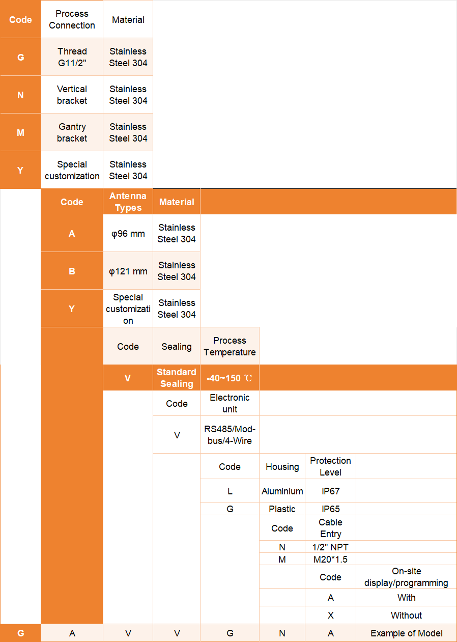
Option Guide:
INQUIRY
CATEGORIES
LATEST NEWS
CONTACT US
Contact:Roxy Deng
Phone:+8617794001501
Tel:+8617794001501
Email:roxy@besteetech.com
Add:Weibin District, Baoji, Shaanxi Province, China
 Roxy Deng
 Roxy Deng